Dc to dc boost converter circuit homemade Study on power electronics, duty cycle of a power electronics system 3.7v to 5v boost converter me2108a33p
Schematic diagram of the proposed high step‐up converter | Download
Bidirectional dc-dc converter circuit diagram 5v to 12v, dc to dc boost converter circuit gadgetronicx Dc to dc step down converter circuit diagram
Dc boost voltage step converters circuits basic
Step up converter basic circuitBest 3.7v to 12v boost converter circuit & modules Dc to dc adjustable step up boost power supply converterCircuit converter boost dc diagram part.
Step up circuit diagramBoost converter dc arduino circuit feedback lm2577 schematic diagram potentiometer electronoobs code circuitos Dc to dc step up converter circuit diagramBoost converters.

A simple dc-dc boost converter circuit using 555 timer ic
Dc step 5v converter 4v circuit schematic volt output electronics lab driver led volts voltages converting extremely low currentDc-dc step up converter Schematic diagram of the proposed high step‐up converterConverter circuit 5v 12v eleccircuit kerja flasher heater vapcap induction input.
12 to 24 volt dc converter circuitsUsb 5v to 12v dc-dc step-up converter circuit Dc converter circuit diagram step using boost 12v 24v simple 12vdc 24vdc volt voltage 24 power circuits ic output wiringDc to dc boost converter circuit homemade.

Circuit diagram step down
Converter 5v 15v circuit lm2577 7v diagram 12v regulator datasheetStep up transformer wiring diagram Dc dc step up converter schematicDc step-up converter schematic.
2.4v to 5v step up dc-dc converterEfficient_regulated_step_up_converter Dc step circuit converter boost simple basic oscillator electronics easy stepup wiring draw oscillators12v to 5v converter circuit diagram.

Boost converter dc diagram circuit step schematic input using output make homemade circuitos feedback electronoobs choose board component boots
Converter schematicBoost converter ayuda Circuit dc converter boost inductor build shown below breadboard above pdfBoost converter circuit 555.
How to build a dc-to-dc boost converter circuitMany circuits: dc to dc converter 2 Boost voltage inductor constant variable capacitorCircuit step converter regulated efficient supply power seekic diagram ic.

Dc-dc step up converter
Dc to dc boost converter circuit (part 5/9)5v buck converter circuit diagram Converter step down dc circuit uc3845 buck boost using schematics circuitsDraw your wiring : simple dc to dc boost up circuit.
Lm2577 boost converter circuitConverter circuit diagram schematic 12v What is boost converter? circuit diagram and working.


5v Buck Converter Circuit Diagram

A Simple DC-DC Boost Converter Circuit using 555 Timer IC

Study on Power Electronics, Duty cycle of a Power Electronics system
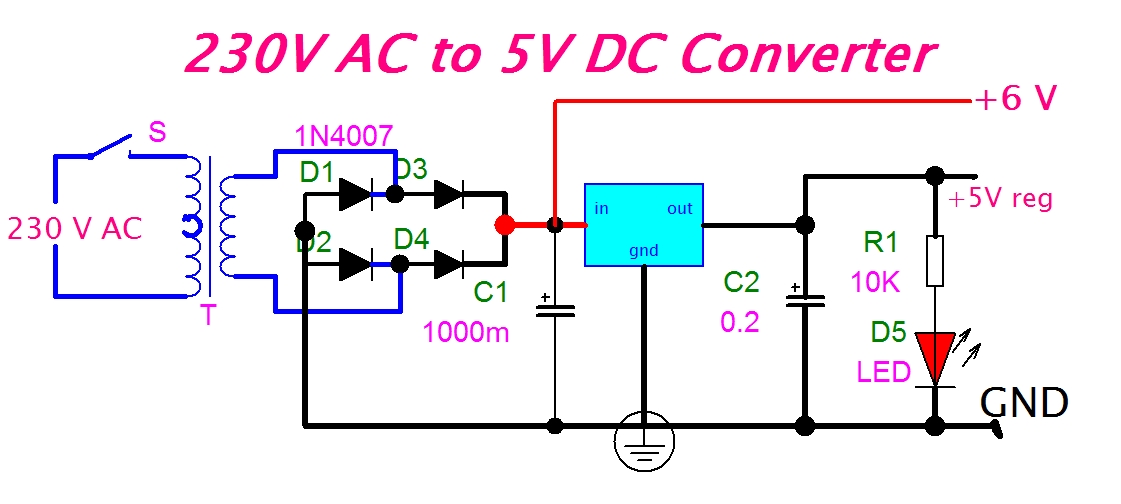
12v To 5v Converter Circuit Diagram

Boost Converter Circuit 555
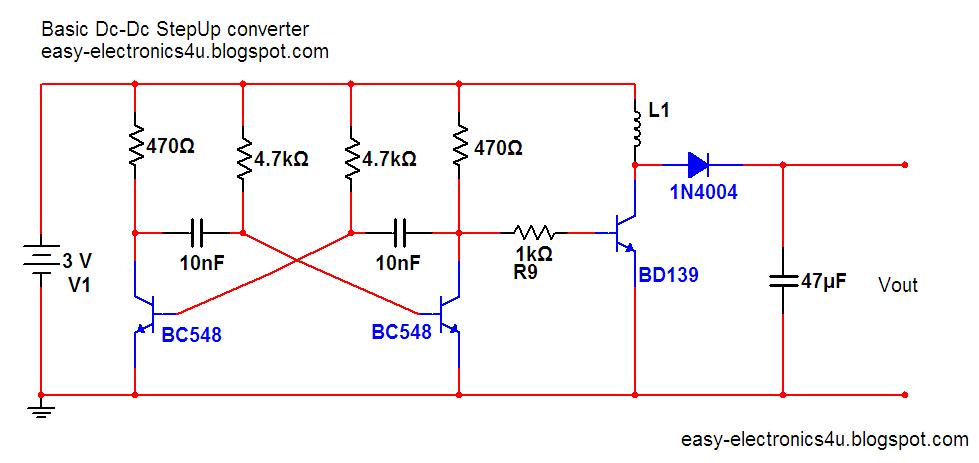
Draw your wiring : Simple Dc To Dc Boost Up Circuit

3.7V to 5V Boost Converter ME2108A33P